Skip to content
Menu

7 Tips to Choose the Right Relief Valve Block?

Selecting the right Relief Valve Block is a small decision with serious consequences. It influences isolation, maintenance, leakage control, and emergency response. A poorly matched block can restrict flow, complicate testing, or create an unnoticed pressure path.

Industry demand is also rising. Grand View Research reported that the global pressure relief valve market was valued at approximately USD 4.7 billion in 2023. Its analysis projects continued growth through 2030, driven by stricter process safety expectations and expanding industrial automation. MarketsandMarkets has likewise identified oil and gas, chemicals, power generation, and water treatment as major application sectors. These figures show opportunity, but they do not replace engineering judgment.

Trevor Kletz, a respected process-safety author, warned, “What you don’t know can hurt you.” That warning fits valve-block selection. Engineers must examine pressure rating, temperature range, wetted materials, port configuration, actuation method, and maintenance access. API 520 and API 521 provide important guidance for pressure-relief-system design, while ASME requirements may apply to the protected equipment. Standards are essential. They are not a substitute for field experience.

A useful selection process should also consider vibration, corrosion, installation space, and accidental misalignment. The smallest detail matters. A blocked vent path can become a dangerous oversight. This guide presents seven practical tips for choosing a Relief Valve Block with greater confidence. Still, no checklist is perfect. Actual media behavior, operating history, and inspection findings may challenge the original design assumptions.
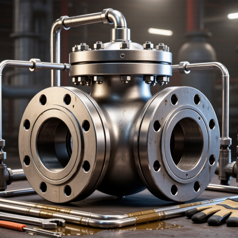
7 Tips to Choose the Right Relief Valve Block?

Understand the Role and Application of a Relief Valve Block

7 Tips to Choose the Right Relief Valve Block?

Understand the Role and Application of a Relief Valve Block

A relief valve block connects a pressure relief valve with the protected system. It helps control, isolate, test, or drain the valve during maintenance. Its main duty is simple: release excess pressure before equipment suffers damage. In hydraulic systems, the block may protect pumps, actuators, and compact power units. In pneumatic systems, it can support receivers, manifolds, and process lines. The application decides the design.

Check the system pressure, temperature, fluid type, and required flow rate. Then match the block’s pressure rating and port size. Material compatibility matters, especially with corrosive fluids or high-temperature oil. Examine the internal passage carefully. A narrow passage can restrict relief flow. That mistake is easy to miss. Confirm the valve connection, thread standard, and installation direction. A small mismatch can create leakage or expensive rework.

Consider access for testing and inspection. A visible test port saves time when technicians verify operating pressure. Choose a block that reduces unnecessary joints and possible leak points. If isolation is possible, use a documented procedure and suitable secondary protection. Never close a valve that could disable the only pressure safeguard. Review certificates, inspection records, and pressure-test evidence from the supplier. Field conditions can differ from drawings, so check the actual space, vibration, and maintenance clearance before ordering. A perfect specification can still fail in a cramped installation.

Match Pressure Ratings and Flow Requirements

7 Tips to Choose the Right Relief Valve Block

Choose a relief valve block by comparing its pressure rating with the system’s maximum allowable working pressure. Never match only the normal operating pressure. Include startup surges, thermal expansion, and pump shutdown spikes. The block should remain structurally safe at the highest credible pressure. Check the datasheet carefully. Pressure ratings can change with temperature.

Flow capacity deserves equal attention. Estimate the required discharge flow, then compare it with the valve block’s rated flow coefficient and port size. A narrow passage can create excessive pressure loss before the valve responds. Flow matters. Consider fluid density, viscosity, temperature, and backpressure during real operation. Gas and liquid systems behave differently, even when their pressure readings look similar.

Confirm that the set pressure suits the protected equipment, not just the pipework. Review inlet and outlet connections for restrictions, vibration, and maintenance access. Verify materials against the process fluid and operating temperature. Test or inspection records add useful evidence of reliability. I have seen selections fail because engineers used steady-state data only. That approach feels efficient, but it can miss short pressure peaks. Recalculate with measured field data when possible, and ask a qualified engineer to review unusual service conditions. Small assumptions can become costly weaknesses.

Select Suitable Materials for Fluid and Operating Conditions

7 Tips to Choose the Right Relief Valve Block?

Select Suitable Materials for Fluid and Operating Conditions

Material choice matters. A relief valve block must tolerate the fluid, pressure, temperature, and surrounding environment. Stainless steel often suits water, chemicals, and humid installations, but its grade still requires careful review. Carbon steel may perform well in dry, controlled systems. Brass can fit some low-pressure services, yet it may be unsuitable for aggressive fluids or high temperatures.

Check chemical compatibility before comparing prices. Review the fluid’s concentration, viscosity, impurities, and possible temperature changes. A clean liquid can become corrosive when heated. Gas service also demands attention to permeability, contamination, and rapid pressure changes. Small details matter. Confirm that the block body, internal passages, threads, and seals match the same service conditions.

During valve-block inspections, engineers often focus on the body material and overlook seals or threaded connections. That shortcut can create leakage later. I would also examine galvanic corrosion when dissimilar metals connect. Do not guess. Use verified material data, pressure-temperature ratings, and fluid compatibility charts. When information is incomplete, request laboratory data or consult a qualified materials engineer. Selection is not always perfect, because real systems may contain moisture, particles, or chemicals missing from the original specification. Build in a reasonable safety margin, then document why the chosen material fits the operating conditions.

Check Port Sizes, Connections, and Installation Space

Choosing a relief valve block requires more than matching the pressure rating. Port size can affect flow capacity, pressure drop, and system response. A small inlet may restrict discharge during a pressure spike. An oversized block can create unnecessary cost and awkward pipe transitions. Check the valve datasheet against the pump or actuator flow rate.

Connection type matters just as much. Confirm whether the system uses threaded, flanged, compression, or cartridge connections. Verify thread standards, sealing methods, and port orientation before ordering. Mixing similar-looking thread profiles is a common field mistake. It may cause leakage or damage during tightening. I once saw a fitting appear correct until the final inspection exposed a mismatched thread. Slow checks prevent expensive rework.

Measure the installation area, not only the block itself. Leave room for a wrench, pressure gauge, adjustment access, and future maintenance. Tubing also needs space for its bend radius. Keep the discharge path short and properly supported. Vibration can loosen poorly supported connections over time. Access matters. A valve hidden behind a frame may be technically installed but difficult to test safely. Review the layout with the installer, then compare it with the assembly drawing and applicable technical requirements.

7 Tips to Choose the Right Relief Valve Block? – Check Port Sizes, Connections, and Installation Space

Tip Selection Dimension What to Check Typical Data or Requirement Why It Matters
1 Confirm the valve port size Match the block inlet and outlet ports with the relief valve and hydraulic circuit. Common nominal port sizes include G1/4, G3/8, G1/2, 1/2 NPT, and 3/4 NPT. The selected size should not be smaller than the required flow path. An undersized port can increase pressure drop, restrict flow, and cause unstable system performance.
2 Verify connection standards Identify the thread form, thread size, sealing method, and connection orientation. Typical standards include ISO 228/G parallel threads, ISO 7-1/Rp or tapered pipe threads, and NPT. Do not mix incompatible thread standards. Correct thread compatibility helps prevent leakage, damaged threads, and difficult maintenance.
3 Check pressure and flow ratings Compare maximum working pressure and rated flow with the application requirements. Select a block whose maximum working pressure is higher than the system operating pressure. For example, a circuit operating at 210 bar should not use a component rated below 210 bar; a safety margin is recommended. Adequate ratings reduce the risk of leakage, deformation, premature wear, or component failure.
4 Evaluate adjustment range Make sure the relief setting range covers the required operating pressure. Common hydraulic relief settings may fall within ranges such as 20–100 bar, 50–210 bar, or 100–315 bar. The desired setting should preferably sit near the middle of the adjustment range. A suitable range supports more precise adjustment and helps avoid operating at the limit of the spring or cartridge.
5 Measure installation space Check overall length, width, height, mounting holes, access clearance, and adjustment direction. Allow practical clearance around the block for tools and maintenance. A typical hand-tool access allowance is approximately 50–75 mm, depending on the adjustment screw, locknut, or protective cap. Sufficient space prevents interference with hoses, manifolds, guards, and nearby equipment during installation or servicing.
6 Select suitable materials and seals Match the body material, surface treatment, and seal compound to the fluid and environment. Common body materials include carbon steel and stainless steel. Nitrile seals are widely used with mineral hydraulic oils, while fluorocarbon seals are often selected for higher-temperature or chemically demanding applications. Always verify chemical compatibility. Proper material selection improves corrosion resistance, temperature performance, service life, and fluid compatibility.
7 Review maintenance and testing requirements Confirm adjustment access, inspection points, replacement parts, and pressure-testing provisions. A practical design should permit connection of a pressure gauge or test point where required. After installation, inspect for leaks and verify the relief setting under controlled operating conditions. Easy testing and adjustment simplify commissioning, troubleshooting, preventive maintenance, and safe pressure control.

Verify Safety Features, Standards, and Maintenance Needs

7 Tips to Choose the Right Relief Valve Block

Start with the actual hazard. Confirm the vessel’s maximum allowable working pressure, operating temperature, fluid, and required flow capacity. Choose a block with a clearly defined set pressure. Check whether the design supports safe isolation, test connections, and controlled discharge. These details are easy to overlook. They should not be.

Verify recognized requirements, including ASME BPVC Section VIII, API 520, API 521, and ISO 4126, where applicable. Ask for material certificates, pressure-test records, and calibration evidence. The U.S. Bureau of Labor Statistics recorded 5,283 fatal work injuries in 2023. That broad figure reinforces one point: small control failures can have serious consequences. Relief equipment needs documented verification, not verbal assurance. I have seen maintenance plans fail because access space was treated as an afterthought.

Inspect the block for corrosion resistance, visible flow direction, locking arrangements, and safe vent routing. Confirm that operators can identify the active valve quickly. Create a maintenance schedule based on service severity, not convenience. Check seals, bolts, threads, and tamper controls during each inspection. The UK Health and Safety Executive reported 138 worker fatalities in 2023/24. This does not measure relief-valve failures, but it keeps risk decisions grounded. A practical weakness remains: many facilities document inspection dates, but not what inspectors actually found. Record test results, changes, and unresolved defects. Train the people who will isolate, test, and return the system to service.

7 Tips to Choose the Right Relief Valve Block

Engineering verification priorities for safety, standards compliance, and maintenance planning

The chart uses a practical 100-point selection checklist. Safety and pressure-control checks receive the greatest weight because relief valve blocks must support correct sizing, set-pressure verification, isolation control, material compatibility, and safe inspection or replacement. Standards such as ASME BPVC Section VIII, API 520, API 521, and ISO 4126 should be reviewed for the specific service and jurisdiction.